My Home Networking Journey: From Hacky Workarounds to a Proper Setup
February 2026 · 15 min read · Written by 🤖 @claude & 🧑 @adityamohta
Note: Some network details (IP addresses, VLAN IDs, subnets, etc.) have been masked for security.
The Old Setup: Making It Work With What I Had
My home network started the way most do in India — with the default Airtel ONT (Optical Network Terminal) router that comes with the fiber connection. It worked, but the coverage wasn't great, so I added a TP-Link router to extend things.
The "Poor Man's Load Balancing"
Here's what I did: I connected the TP-Link router to the Airtel ONT via an Ethernet cable and ran it in LAN mode (not bridge mode). Then I set the SSID and password on both routers to be exactly the same.
The idea was simple — if a device got dropped by one router, it would automatically reconnect to the other since the credentials were identical. A sort of DIY seamless roaming.
graph TD
    ISP["🌐 Airtel Fiber (ISP)"]
    ONT["Airtel ONT Router
SSID: MyWiFi
Gateway: 192.168.X.1"]
    TPLink["TP-Link Router (LAN Mode)
SSID: MyWiFi
Gateway: 192.168.Y.1"]

    ISP -->|Fiber| ONT
    ONT -->|Ethernet| TPLink

    subgraph "Devices on Airtel ONT"
        D1["📱 Phone"]
        D2["💻 Laptop"]
    end

    subgraph "Devices on TP-Link"
        D3["📺 TV"]
        D4["🎮 Console"]
    end

    ONT --> D1
    ONT --> D2
    TPLink --> D3
TPLink --> D4The Problems
This setup had a few issues I lived with for a while:
1. Double NAT / Extra Network Hop
Since the TP-Link was running in LAN mode (not bridge mode), it was essentially acting as a second router with its own subnet. Devices connected to the TP-Link had to go through two routers before reaching the internet — double NAT.
I could confirm this by running traceroute:
From a device connected to the Airtel ONT (1 hop to gateway):
$ traceroute google.com
traceroute to google.com (142.250.195.206), 30 hops max, 60 byte packets
 1  192.168.X.1 (192.168.X.1)  1.234 ms  1.112 ms  1.045 ms
 2  * * *
 3  ...
From a device connected to the TP-Link (2 hops — extra hop through TP-Link's gateway):
$ traceroute google.com
traceroute to google.com (142.250.195.206), 30 hops max, 60 byte packets
 1  192.168.Y.1 (192.168.Y.1)  0.987 ms  0.854 ms  0.812 ms
 2  192.168.X.1 (192.168.X.1)  2.345 ms  2.123 ms  2.067 ms
 3  * * *
 4  ...
That extra hop (192.168.Y.1 → 192.168.X.1) meant added latency for every request from TP-Link-connected devices.
2. Two Separate Subnets
Devices on the Airtel ONT (192.168.X.x) and devices on the TP-Link (192.168.Y.x) were on different subnets. This meant:
- Devices couldn't easily discover each other (e.g., Chromecast on one router, phone on the other)
- File sharing / local services were unreliable
- AirDrop, printer discovery, and similar mDNS-based features were hit or miss
graph LR
    subgraph "Subnet 192.168.X.x (Airtel ONT)"
        A1["Phone
192.168.X.101"]
        A2["Laptop
192.168.X.102"]
    end

    subgraph "Subnet 192.168.Y.x (TP-Link)"
        B1["TV
192.168.Y.101"]
        B2["Console
192.168.Y.102"]
    end

    A1 -.-x|"❌ Can't discover"| B1
A2 -.-x|"❌ Can't discover"| B23. Not True Roaming
Even though the SSIDs matched, this wasn't real seamless roaming. Devices would often stubbornly hold on to a weak signal from one router instead of switching to the stronger one nearby. There was no coordination between the two routers — no 802.11r fast roaming, no centralized controller telling devices to hand off.
graph TD
    subgraph "What I Expected"
        E1["📱 Walk from Room A to Room B"] --> E2["Seamless handoff to closer AP"]
    end

    subgraph "What Actually Happened"
        R1["📱 Walk from Room A to Room B"] --> R2["Still clinging to weak signal
from Room A's router"]
        R2 --> R3["Eventually disconnects"]
        R3 --> R4["Reconnects to Room B's router
(after a noticeable gap)"]
endThe Network Topology (Old Setup)
Here's how the full picture looked:
flowchart TD
    ISP["🌐 Airtel Fiber"]
    ONT["Airtel ONT Router
192.168.X.1
WiFi + DHCP + NAT"]
    TPLink["TP-Link Router
192.168.Y.1
WiFi + DHCP + NAT"]
    Internet["Internet"]

    Internet --> ISP
    ISP -->|Fiber| ONT
    ONT -->|"Ethernet (WAN port)"| TPLink

    ONT -.->|"WiFi: MyWiFi"| DevA["Devices A"]
    TPLink -.->|"WiFi: MyWiFi"| DevB["Devices B"]

    DevB -->|"Hop 1: 192.168.Y.1"| TPLink
    TPLink -->|"Hop 2: 192.168.X.1"| ONT
    ONT -->|"To Internet"| ISP

    style ONT fill:#161b22,stroke:#238636,color:#3fb950
style TPLink fill:#161b22,stroke:#da3633,color:#f85149Why I Even Needed Two Routers
It wasn't just about coverage. My home had around 25 devices on the network, out of which roughly 15 were IoT devices — smart lights, plugs, assistants, you name it.
The Airtel ONT router simply couldn't handle that many concurrent connections. It has about 128 MB of DDR3 RAM — fine for a handful of phones and laptops, but nowhere near enough for 25 devices all chattering on the network. I'd frequently hit:
- Network slowdowns — pages loading sluggishly even on a 100+ Mbps fiber connection
- Random dropouts — devices just falling off the network and needing to reconnect
- IoT devices becoming unresponsive — smart home automations failing because a device went offline
Adding the TP-Link router helped spread the load, but it was a band-aid, not a fix.
It worked. Mostly. But I knew it could be better.
The New Setup: Going UniFi
I don't have a networking background. I didn't want to dig into the network controllers of the Airtel ONT or tinker with the TP-Link router's advanced settings. What I wanted was:
- A machine that was significantly more powerful than these consumer routers
- An excellent network controller with a proper management UI
- Something scalable — my home is only growing in IoT devices
- Security — proper firewall, traffic inspection, VLAN support for isolating IoT devices
A co-worker who's a UniFi fan introduced me to the Ubiquiti/UniFi ecosystem. The more I looked into it, the more it checked every box. After some research, I landed on a starter kit:
The Shopping List
| Device | Role | Why |
|---|---|---|
| UniFi Cloud Gateway Ultra | Internet gateway + network controller | Runs the UniFi Network app, handles routing, firewall, DHCP — the brain of the network |
| UniFi U6+ | WiFi 6 access point | Proper AP with centralized management, 802.11r roaming support, and band steering |
| 15W PoE Adapter | Powers the U6+ | Saved money by skipping the UniFi Switch Ultra for now — all my devices are on WiFi anyway |
graph TD
    subgraph "What I Bought"
        CGU["Cloud Gateway Ultra
Gateway + Controller
~Rs. 12,000"]
        U6["U6+ Access Point
WiFi 6
~Rs. 11,000"]
        POE["15W PoE Adapter
Powers the U6+
~Rs. 1,000"]
    end

    CGU -->|"Ethernet"| POE
    POE -->|"PoE (Power + Data)"| U6

    style CGU fill:#161b22,stroke:#238636,color:#3fb950
    style U6 fill:#161b22,stroke:#58a6ff,color:#79c0ff
style POE fill:#161b22,stroke:#8b949e,color:#c9d1d9I skipped the UniFi Switch Ultra initially to keep costs down. Since all my devices connect via WiFi, a dedicated switch wasn't a priority. The PoE adapter does the job of powering the U6+ for now.
The Target Topology
The new setup would be straightforward:
Airtel ONT → Cloud Gateway Ultra → U6+
But there was a catch.
The Bridge Mode Battle
I didn't want WiFi running on the Airtel ONT router anymore. Leaving it active would be a security hole — an unmanaged network sitting alongside my carefully configured UniFi setup. I wanted the Cloud Gateway Ultra to be the single point of control for all traffic.
But the Airtel router wasn't just an ONT — it was an ONT + router. Which meant double NAT was back:
flowchart LR
    Internet["🌐 Internet"]
    ONT["Airtel ONT+Router
NAT #1
192.168.X.1"]
    CGU["Cloud Gateway Ultra
NAT #2
192.168.X.1"]
    U6["U6+"]
    Devices["All Devices"]

    Internet --> ONT
    ONT -->|"Double NAT 😤"| CGU
    CGU --> U6
    U6 -.-> Devices

    style ONT fill:#161b22,stroke:#da3633,color:#f85149
style CGU fill:#161b22,stroke:#238636,color:#3fb950I needed the Airtel router to act as a dumb ONT — just convert the fiber signal to Ethernet and pass it through without any routing, NAT, or DHCP. In other words: bridge mode.
Getting Airtel to Enable Bridge Mode
I checked the Airtel router's admin panel and found an option to put a single LAN port into bridge mode. Great! Except... it didn't work. Traffic wasn't passing through to the Cloud Gateway Ultra properly.
That's when the real fun began — calling Airtel support.
After a lot of back and forth (multiple calls, explaining what bridge mode is to different support agents, being transferred around), I finally got them to enable bridge mode on a dedicated LAN port from their end.
sequenceDiagram
    participant Me
    participant Airtel Support
    participant Airtel Router

    Me->>Airtel Support: I need bridge mode on a LAN port
    Airtel Support->>Me: Have you tried restarting the router?
    Me->>Airtel Support: Yes. I need bridge mode enabled from your end.
    Airtel Support->>Me: Let me transfer you to L2 support...
    Note over Me,Airtel Support: ...multiple calls later...
    Airtel Support->>Airtel Router: Enable bridge mode on LAN port
    Airtel Router->>Me: Bridge mode active ✅
Me->>Me: 🎉Once bridge mode was enabled, the Airtel router became just an ONT — bridging all network traffic directly to my UniFi Cloud Gateway Ultra. No more double NAT, no more rogue DHCP server, no more unmanaged WiFi.
The New Topology
flowchart TD
    Internet["🌐 Internet"]
    ISP["Airtel Fiber"]
    ONT["Airtel ONT
(Bridge Mode)
Just converts fiber ↔ ethernet"]
    CGU["UniFi Cloud Gateway Ultra
Router + Firewall + DHCP + Controller
192.168.X.1"]
    POE["15W PoE Adapter"]
    U6["UniFi U6+
WiFi 6 Access Point"]

    Internet --> ISP
    ISP -->|Fiber| ONT
    ONT -->|"Ethernet (Bridged)"| CGU
    CGU -->|Ethernet| POE
    POE -->|"PoE (Power + Data)"| U6

    U6 -.->|"WiFi 6"| D1["📱 Phones"]
    U6 -.->|"WiFi 6"| D2["💻 Laptops"]
    U6 -.->|"WiFi 6"| D3["📺 Smart TVs"]
    U6 -.->|"WiFi 6"| D4["💡 IoT Devices"]

    style ONT fill:#161b22,stroke:#8b949e,color:#c9d1d9
    style CGU fill:#161b22,stroke:#238636,color:#3fb950
    style U6 fill:#161b22,stroke:#58a6ff,color:#79c0ff
style POE fill:#161b22,stroke:#30363d,color:#8b949eNo extra hops. Single subnet. One controller managing everything. And a traceroute that finally looked clean:
$ traceroute google.com
traceroute to google.com (142.250.195.206), 30 hops max, 60 byte packets
 1  192.168.X.1 (192.168.X.1)  0.652 ms  0.543 ms  0.498 ms
 2  * * *
 3  ...
One hop to the gateway. As it should be.
Planning the Access Point Placement
With the hardware ready, the next question was: where do I mount the U6+?
This mattered more than it sounds. My home has a mix of devices with very different WiFi needs:
- IoT devices (smart lights, plugs, sensors) — these almost exclusively use 2.4 GHz. They need range and wall penetration, not speed.
- Media/work devices (laptops, TVs, phones) — these benefit from 5 GHz for faster speeds, but 5 GHz has shorter range and struggles with thick walls.
I needed to find a spot where the U6+ could blanket the IoT devices on 2.4 GHz while still delivering strong 5 GHz to the rooms where I work and consume media.
UniFi Design Center (InnerSpace)
Rather than guessing and drilling holes, I used UniFi's InnerSpace tool — their built-in network design planner. Here's what I did:
- Uploaded a 2D floor plan of my home
- Drew in the concrete walls (this is important — concrete attenuates signal significantly more than drywall)
- Switched to 3D mode to visualize signal propagation
- Dragged the AP around the floor plan, watching the 2.4 GHz and 5 GHz coverage heatmaps update in real time
Here's a preview of me planning the placement in InnerSpace:
After moving the AP around in the 3D view and checking both bands, I finalized the location — a central spot that maximized 2.4 GHz reach to the far corners (where most IoT devices sit) while keeping 5 GHz strong in the living room and office areas.
graph TD
    subgraph "2.4 GHz Coverage (Long Range)"
        IOT1["💡 Smart Lights"]
        IOT2["🔌 Smart Plugs"]
        IOT4["🌡️ Sensors"]
    end

    subgraph "5 GHz Coverage (High Speed)"
        MEDIA1["💻 Laptops"]
        MEDIA2["📺 Smart TVs"]
        MEDIA3["📱 Phones"]
        MEDIA4["🎮 Console"]
    end

    AP["UniFi U6+
Central Location"]

    AP -.->|"2.4 GHz
Better range through walls"| IOT1
    AP -.->|"2.4 GHz"| IOT2
    AP -.->|"2.4 GHz"| IOT4
    AP -->|"5 GHz
Faster speeds, shorter range"| MEDIA1
    AP -->|"5 GHz"| MEDIA2
    AP -->|"5 GHz"| MEDIA3
    AP -->|"5 GHz"| MEDIA4

style AP fill:#161b22,stroke:#58a6ff,color:#79c0ffLocking Down the Network: VLANs
With the AP placed and all 25+ devices happily connected, the next priority was security. Specifically — I didn't want all my devices on the same network.
Why Isolate IoT Devices?
Here's the thing about IoT devices: I don't fully trust them. These are cheap smart plugs and sensors made by various manufacturers. Any one of them could:
- Have unpatched vulnerabilities
- Phone home to sketchy servers
- Be compromised and used as a pivot point to attack other devices on the network
If a smart bulb gets hacked, I don't want it to have access to my laptop, my phone, or my NAS. The answer: VLANs (Virtual Local Area Networks) — logically separate networks running on the same physical hardware.
My VLAN Setup
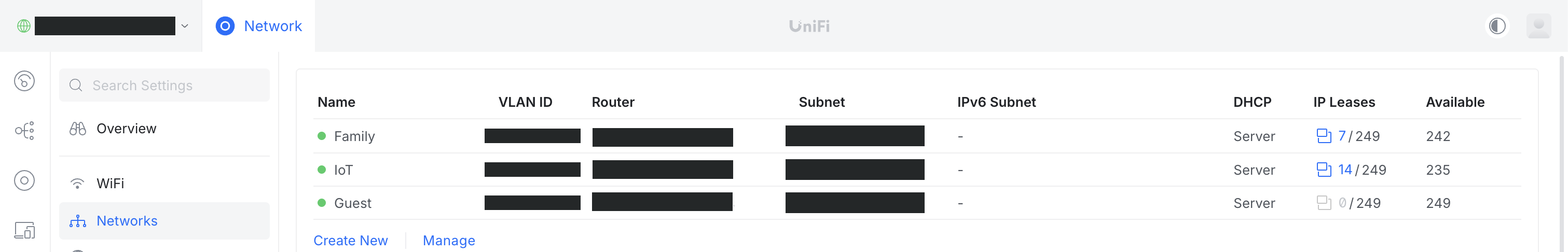
I created 3 VLANs in the UniFi controller:
| Name | VLAN ID | Subnet | Purpose |
|---|---|---|---|
| Family | ~redacted~ | Trusted devices — laptops, phones, work machines | |
| IoT | ~redacted~ | Smart home devices — lights, plugs, sensors | |
| Guest | ~redacted~ | Visitors — internet only, no local access |
Here's how it looks in the UniFi Network dashboard:
flowchart LR
    CGU["Cloud Gateway Ultra
Router + Firewall"]

    subgraph VLANA["Family"]
        F1["💻 Laptop"] & F2["📱 Phone"] & F3["🖥️ Desktop"]
    end

    subgraph VLANB["IoT"]
        I1["💡 Lights"] & I2["🔌 Plugs"] & I4["🌡️ Sensors"]
    end

    subgraph VLANC["Guest"]
        G1["📱 Guest Phone"] & G2["💻 Guest Laptop"]
    end

    CGU -->|"✅ Full access"| VLANA
    CGU -->|"🔒 Internet only"| VLANB
    CGU -->|"🔒 Internet only"| VLANC

    VLANA -.-x|"🚫"| VLANB
    VLANA -.-x|"🚫"| VLANC
    VLANB -.-x|"🚫"| VLANC

    style VLANA fill:#161b22,stroke:#238636,color:#3fb950
    style VLANB fill:#161b22,stroke:#da3633,color:#f85149
style VLANC fill:#161b22,stroke:#a371f7,color:#d2a8ffWhat This Means in Practice
- Family devices can see each other (AirDrop, file sharing, Chromecast — all work)
- IoT devices can reach the internet (for cloud services, firmware updates) but cannot talk to Family or Guest devices
- Guest devices get internet access and nothing else — they can't see any local device
- Even if an IoT device gets compromised, the attacker is trapped in the IoT VLAN with no route to my personal devices
Each VLAN gets its own WiFi SSID in the UniFi controller, so devices automatically join the right network.
Region Blocking
One of the perks of having a proper gateway is being able to block traffic to and from entire countries at the network level. The Cloud Gateway Ultra makes this ridiculously easy with its built-in Region Blocking feature.
Why Block Regions?
Most of my IoT devices don't need to talk to servers in countries I have no business communicating with. Blocking traffic from high-risk regions reduces the attack surface — if a compromised device tries to phone home to a command-and-control server in a blocked country, the connection gets dropped at the firewall before it ever leaves my network.
It's not a silver bullet, but it's a low-effort, high-value layer of defense.
Setting It Up
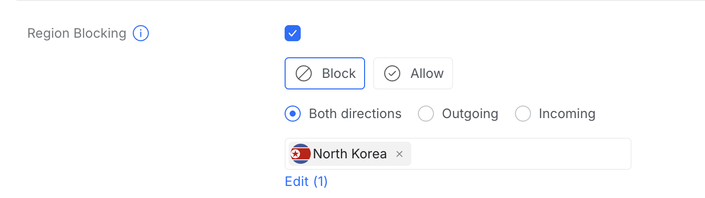
In the UniFi Network controller, it's literally a toggle + a country picker:
- Enable Region Blocking
- Choose Block mode
- Set direction to Both directions (blocks both incoming and outgoing traffic)
- Add the countries you want to block
That's it. No manual firewall rules, no IP lists to maintain — UniFi handles the geo-IP database and keeps it updated.
Here's what it looks like in the dashboard:
What I Blocked
I started with a conservative list of countries that my devices have zero reason to communicate with — regions known for high volumes of malicious traffic and state-sponsored cyber activity. The list will likely grow as I review traffic logs.
The beauty of this approach is that it's set and forget. The gateway silently drops matching traffic without any performance impact on legitimate connections.
Failover Network: Mobile Hotspot as Backup Internet
I didn't want to spend money on a second ISP — Airtel fiber is pretty stable for me. But on the rare occasion it does go down (maintenance, outage, cable cut), I wanted the entire home network to keep working without anyone having to reconfigure anything.
The Cloud Gateway Ultra has 4 × 1 Gbps LAN ports and 1 × 2.5 Gbps WAN port, but it also lets you reconfigure LAN ports as additional WAN ports. That means you can plug in multiple internet sources and set up failover or load balancing. I went with failover.
The Idea
Use my phone's mobile hotspot as a backup internet connection. When Airtel goes down, just turn on the hotspot and the whole home network switches over automatically.
But there's a problem — the Cloud Gateway Ultra takes Ethernet input, not WiFi. I needed a way to convert the hotspot's WiFi signal into an Ethernet connection.
The Rs. 900 Solution: A Cheap WiFi Repeater
I bought a cheap WiFi repeater that had an output LAN port (~Rs. 900). Here's the trick:
- Configured the repeater to repeat a WiFi network called "Failover" (not the actual SSID — use something unique and non-obvious for yours)
- Set my phone's hotspot SSID and password to exactly "Failover" (matching what the repeater expects)
- Connected the repeater's LAN port to the Cloud Gateway Ultra's WAN3 port
- Left the repeater powered on permanently
Now, whenever I (or my wife) turn on the mobile hotspot, the repeater connects to it within seconds, and internet flows through to the gateway via Ethernet.
flowchart LR
    Phone["📱 Phone
Hotspot: 'Failover'
5G (~30-35 Mbps)"]
    Repeater["WiFi Repeater
(~Rs. 900)
Repeats 'Failover' SSID"]
    CGU["Cloud Gateway Ultra
WAN3"]

    Phone -.->|"WiFi"| Repeater
    Repeater -->|"Ethernet"| CGU

    style Phone fill:#161b22,stroke:#58a6ff,color:#79c0ff
    style Repeater fill:#161b22,stroke:#8b949e,color:#c9d1d9
style CGU fill:#161b22,stroke:#238636,color:#3fb950Configuring the WAN Ports
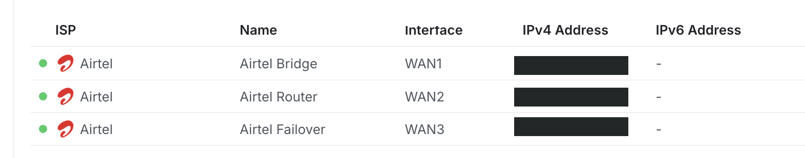
The Cloud Gateway Ultra now has three WAN connections:
| Port | Name | Purpose |
|---|---|---|
| WAN1 | Airtel Bridge | Primary internet — Airtel ONT in bridge mode (gets a public IP) |
| WAN2 | Airtel Router | Airtel ONT in LAN/router mode — kept for admin access to the ONT's management page in rare cases |
| WAN3 | Airtel Failover | Backup internet — WiFi repeater connected to mobile hotspot |
Here's the WAN ports configuration in the UniFi controller:
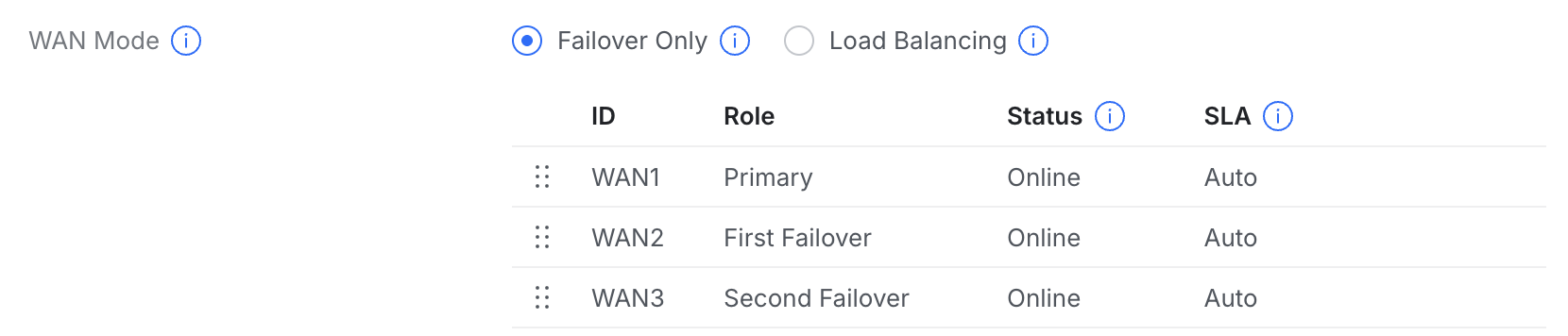
Failover Only Mode
In the WAN settings, I set the mode to Failover Only (not Load Balancing). This means:
- WAN1 is the Primary — all traffic goes through Airtel fiber
- WAN2 is First Failover — if WAN1 goes down, traffic routes through the Airtel router (non-bridged) connection
- WAN3 is Second Failover — if both WAN1 and WAN2 fail (full Airtel outage), traffic routes through the mobile hotspot
The Doomsday Scenario
If Airtel goes down completely:
- I or my wife turn on the phone's mobile hotspot
- The WiFi repeater connects to it within seconds
- The Cloud Gateway Ultra detects internet on WAN3 and automatically fails over
- All 25+ devices in the home continue working — on 5G speeds (~30-35 Mbps, plenty for a temporary fallback)
- When Airtel comes back, the gateway automatically switches back to WAN1
No reconfiguring devices, no switching WiFi networks, no downtime panic. Just flip on the hotspot and walk away.
The Complete Network Topology
Here's the full picture of everything put together — from the ISP to the VLANs, including the failover path:
flowchart TD
    Internet["🌐 Internet"]
    ISP["Airtel Fiber"]
    ONT["Airtel ONT
(Bridge Mode)
(Other ports: Router Mode)"]

    Phone["📱 Phone Hotspot
'Failover' SSID
5G Backup"]
    Repeater["WiFi Repeater
Repeats 'Failover'
Outputs Ethernet"]

    CGU["UniFi Cloud Gateway Ultra
Router + Firewall + Controller
Region Blocking · Failover · VLANs"]

    POE["15W PoE Adapter"]
    U6["UniFi U6+
WiFi 6 Access Point"]

    Internet --> ISP
    ISP -->|Fiber| ONT
    ONT -->|"WAN1 (Bridge)"| CGU
    ONT -->|"WAN2 (Router)"| CGU
    Phone -.->|WiFi| Repeater
    Repeater -->|"WAN3 (Failover)"| CGU

    CGU -->|Ethernet| POE
    POE -->|PoE| U6

    subgraph VLANA["Family"]
        F1["💻 Laptops"]
        F2["📱 Phones"]
        F3["🖥️ Desktop"]
    end

    subgraph VLANB["IoT"]
        I1["💡 Smart Lights"]
        I2["🔌 Smart Plugs"]
        I4["🌡️ Sensors"]
    end

    subgraph VLANC["Guest"]
        G1["📱 Guest Devices"]
    end

    U6 -.->|WiFi 6| VLANA
    U6 -.->|WiFi 6| VLANB
    U6 -.->|WiFi 6| VLANC

    style ONT fill:#161b22,stroke:#8b949e,color:#c9d1d9
    style CGU fill:#161b22,stroke:#238636,color:#3fb950
    style U6 fill:#161b22,stroke:#58a6ff,color:#79c0ff
    style POE fill:#161b22,stroke:#30363d,color:#8b949e
    style Phone fill:#161b22,stroke:#a371f7,color:#d2a8ff
    style Repeater fill:#161b22,stroke:#8b949e,color:#c9d1d9
    style VLANA fill:#161b22,stroke:#238636,color:#3fb950
    style VLANB fill:#161b22,stroke:#da3633,color:#f85149
style VLANC fill:#161b22,stroke:#a371f7,color:#d2a8ffTo be continued — next up: setting up a VPN server...